Walk onto any active construction site and you will find engineers, foremen, and contractors all gathered around the same set of drawings. These people may speak different languages, work for different firms, and hold different qualifications — yet every one of them can extract the same information from those sheets. That shared understanding is made possible by structural drawing symbols.
Structural drawing symbols are standardised graphical marks, lines, abbreviations, and annotations used to represent physical elements — steel bars, columns, slabs, foundations, connections — on technical drawings. Rather than writing out long descriptions for every element, engineers condense that information into precise symbols that occupy a fraction of the space but carry the full meaning.
Civil and structural engineers use symbols for three practical reasons. First, they save space: a drawing showing every reinforced concrete detail in plain text would be unreadable. Second, they eliminate ambiguity: a symbol defined once in a legend means the same thing throughout the entire drawing set. Third, they function as a cross-border, cross-language shorthand, which is why a structural engineer in Lagos can pick up a drawing prepared in London and still interpret the reinforcement layout.
On construction sites, symbols drive execution. A bar bending schedule, for example, relies entirely on correct symbol interpretation to produce the right bar shapes. Misread one annotation and the result is wasted steel, rework, or — in serious cases — a structural deficiency that only becomes visible when loads are applied.
This guide covers every major category of structural drawing symbols: general graphic symbols, reinforcement notations, member labels, slab and floor marks, foundation types, connection symbols, material hatching, and line types. It also walks through how to read drawings step by step, common interpretation mistakes, the software tools that produce these drawings, and the international standards that govern them.

Why Understanding Drawing Symbols Is Important
Construction errors are costly in money, time, and sometimes in lives. A large percentage of site-level mistakes trace back to drawing misinterpretation rather than faulty design. When a contractor places bars at 200 mm spacing because they misread a notation that called for 150 mm, the slab carries less reinforcement than the engineer calculated. The structure may pass visual inspection but be understrength when loaded.
Beyond individual errors, drawing symbols serve as the primary communication channel between the structural engineer, the architect, the geotechnical consultant, and the contractor. Each party reads the same set of drawings and must extract consistent information. When a symbol is misread by any one party, the information chain breaks and coordination fails.
Structural safety is directly connected to symbol accuracy. Foundation drawings, for instance, use specific symbols to indicate pile positions, pile caps, and load transfer mechanisms. A misinterpreted foundation symbol can mean a pile is placed in the wrong location, altering load distribution across the entire structure.
In real practice, engineers and site supervisors report cases where:
- Column starter bars were placed at wrong positions because the column grid reference was read incorrectly.
- Slab reinforcement was laid in one direction only when two-way reinforcement was required, because the span direction arrows were ignored.
- Footings were excavated to the wrong depth because the GL (Ground Level) symbol was confused with the FFL (Finished Floor Level) mark.
Understanding symbols is not optional knowledge reserved for draughtsmen. Every graduate engineer, site supervisor, quantity surveyor, and project manager who works in construction needs working familiarity with these conventions.
Types of Structural Drawings Where Symbols Are Used
General Arrangement (GA) Drawings
GA drawings show the overall layout of a structure — floor plans, roof plans, and site plans. They use grid lines, column position marks, member labels (B1, C3, etc.), and level marks to establish the spatial framework from which all detailed drawings reference.
Reinforcement Drawings
These are the most symbol-dense drawings in a structural set. They carry bar diameter notations (Ø), spacing callouts, T&B indicators, bar mark numbers, lap lengths, and cover dimensions. A single reinforced concrete beam can carry a dozen distinct symbol types on one detail.
Structural Detail Drawings
Detail drawings zoom into connection points, joint conditions, and specific member cross-sections. They show welded connections, bolt patterns, rebar hooks, and construction joints using specialised symbols that do not appear on GA drawings.
Foundation Layout Drawings
Foundation drawings locate footings, pile caps, grade beams, and raft slabs relative to the column grid. They use foundation-specific symbols to differentiate isolated footings from combined footings and pile arrangements.
Section and Elevation Drawings
Sections cut through the structure to show internal conditions — how a beam frames into a column, how a slab connects to a wall, or how a staircase is constructed. Elevation drawings show the external face of walls and facades, using hatching to indicate materials and dimension lines to indicate heights.
Basic Elements of Structural Drawings
Title Block
Every structural drawing carries a title block, usually positioned in the lower right corner. It records the project name, drawing title, drawing number, scale, revision status, date, and the name and stamp of the responsible engineer. Before reading any symbol on a drawing, confirm you are looking at the correct revision — an outdated sheet can carry obsolete information.
Grid Lines and References
Grid lines are a network of numbered and lettered reference lines that criss-cross the plan view of a building. Column A-1 sits at the intersection of grid line A and grid line 1. Every structural element is located relative to this grid, making it possible to pinpoint any member on site without measurements alone.
Dimensions and Levels
Dimension lines show distances between elements and overall span lengths. Level marks (shown as an arrow with a number) indicate heights relative to a defined datum — usually Finished Floor Level (FFL) or an Ordnance Survey datum. These must be read carefully because all vertical positioning of beams, slabs, and columns depends on them.
Notes and Legend
The notes section on a drawing contains text instructions that apply across the entire sheet. The legend — sometimes called the symbol schedule — defines every graphical symbol used on that drawing. Always read the legend before interpreting individual symbols, as some projects use project-specific conventions that vary from international standards.
Common Structural Drawing Symbols and Their Meanings
General Symbols
| Symbol | Name | Meaning / Use |
| ─ ─ ─ (long dash-dot) | Centre Line (CL or ℄) | Marks the axis of symmetry of a structural member or space |
| ←|→ | Dimension Line | Shows the measured distance between two points |
| A-A or B-B with arrows | Section Line | Indicates where a cross-section cut is taken; match the label to the section detail |
| ▽ with number | Level Mark | Identifies a structural or finished level relative to a datum (e.g., ▽+3.500) |
| Zig-zag or double parallel lines | Cut Line / Break Line | Shows that the drawing cuts the element short — the actual element continues beyond |
Reinforcement (Rebar) Symbols
Reinforcement symbols are the most frequently encountered symbols in structural drawings. Understanding them directly affects how bars are cut, bent, and placed on site.
| Symbol / Notation | Meaning |
| Ø16 or T16 or Y16 | High-yield deformed bar with 16 mm diameter |
| R10 or Ø10 (mild steel) | Mild steel round bar with 10 mm diameter |
| 10Ø16 @ 150 c/c | 10 bars, each 16 mm dia., spaced at 150 mm centre-to-centre |
| T&B | Top and Bottom — reinforcement is required at both the top and bottom face of the member |
| EW or E.W. | Each Way — reinforcement runs in both perpendicular directions |
| EF or E.F. | Each Face — reinforcement is placed on both outer faces of a wall |
| Hook (90° or 135°) | Standard end hook to develop bar anchorage at supports |
| Chair bar symbol | A spacer bar that maintains the correct cover depth for top reinforcement |
| Mesh notation (e.g., A393) | Welded wire fabric; the code references the wire spacing and diameter |
Site tip: When a drawing shows ’10T16-01 @ 150 B2′, read it as: 10 bars, type T16, bar mark 01, spaced at 150 mm, placed at Bottom, in direction 2. Each part of that notation carries a specific instruction.
Structural Member Symbols
Structural members are labelled with a letter prefix followed by a number. The letter identifies the member type and the number distinguishes between members of the same type within the project.
| Label | Member Type | Example |
| B | Beam | B1, B2, B3 — each number refers to a unique beam size or position |
| C | Column | C1, C2 — columns of the same designation share dimensions and reinforcement |
| S | Slab | S1, S2 — different slab panels or slab types |
| F | Footing / Foundation | F1, F2 — isolated pad footings of specific sizes |
| W | Wall | W1, W2 — shear walls or retaining walls |
| GL | Grade Beam / Ground Beam | GL1 — a beam at ground level connecting footings |
Slab and Floor Symbols
| Symbol | Meaning |
| Arrow on slab plan | Span direction — the arrow points along the shorter span, indicating the primary reinforcement direction |
| DS or ‘Dep. Slab’ | Depressed slab — the slab surface drops below the general slab level, often for wet areas like bathrooms |
| Opening or void box | Slab opening — a rectangular or circular hole left in the slab for pipes, ducts, or stairs |
| Double arrow (two-way) | Two-way slab — reinforcement runs in both perpendicular directions |
| Single arrow (one-way) | One-way slab — reinforcement runs primarily in the shorter span direction |
Foundation Symbols
| Foundation Type | Drawing Symbol / Representation |
| Isolated / Pad Footing | Single rectangle at a column grid point, labelled F1, F2, etc. |
| Combined Footing | Elongated rectangle spanning two or more column positions |
| Raft / Mat Foundation | Hatched area covering the full plan footprint of the building |
| Pile Foundation | Circle (pile) with X through it, grouped under a pile cap rectangle |
| Strip Footing | Continuous rectangle running under a wall line |
Structural Connection Symbols
| Symbol | Connection Type | Meaning |
| Solid circle at node | Moment / Fixed Connection | The joint transfers both shear and bending moment — the members are rigidly connected |
| Open circle / pin at node | Hinged / Pinned Connection | The joint transfers shear only; it cannot resist rotation, so no bending moment is transferred |
| Diagonal cross-hatching between frames | Braced Frame | A diagonal member or plate provides lateral resistance to horizontal forces like wind |
| Cantilever notation with no support at free end | Cantilever Connection | One end is fully fixed to resist bending; the other end is free |
Material Symbols
Material hatching patterns appear on sections and details to show what material makes up each part of the structure. These patterns are widely standardised but the legend always takes precedence.
| Hatching Pattern | Material |
| Diagonal lines at 45° | Concrete (plain or reinforced) |
| Diagonal cross-hatching | Steel section or plate |
| Staggered brick pattern | Masonry (brickwork or blockwork) |
| Triangular or irregular pattern | Earth / compacted fill / soil |
| Horizontal lines | Timber or wood |
| Wavy horizontal lines | Insulation or waterproofing layer |
Line Types and Their Meanings
| Line Type | Appearance | Meaning |
| Continuous / Solid | Unbroken line | Visible edge of a structural element as seen from the viewing direction |
| Dashed / Hidden | Short equal dashes | Edge or element hidden behind another element from the viewing direction |
| Centre Line | Long dash then dot, repeating | Axis of symmetry of a member, grid line, or bolt hole |
| Phantom Line | Long dash then two dots | Indicates an alternate position or a moved object |
| Property / Boundary Line | Long dash then two short dashes | Site boundary or property demarcation |
Abbreviations Used Alongside Symbols
Abbreviations appear throughout structural drawings alongside symbols. Learning the most common ones removes a major barrier to confident drawing interpretation.
| Abbreviation | Full Form | Context |
| RCC | Reinforced Cement Concrete | Structural members made of concrete with embedded steel bars |
| PCC | Plain Cement Concrete | Concrete without reinforcement, used for blinding or levelling |
| CLR / CV | Clear Cover | The clear distance from the outer face of concrete to the nearest bar surface |
| GL | Ground Level | The natural or existing ground surface level |
| FFL | Finished Floor Level | The final top surface of a floor, after all finishes |
| SFL | Structural Floor Level | The top of the structural slab, before finishes |
| DPC | Damp Proof Course | A horizontal barrier against rising moisture |
| c/c | Centre to Centre | Spacing measurement taken between centrelines of adjacent bars or members |
| NTS | Not to Scale | The drawing is schematic and dimensions should be taken from figures, not scaled |
| T.O.W. | Top of Wall | The elevation at the highest point of a wall |
| B.O.F. | Bottom of Footing | The elevation at the underside of a foundation element |
| Ø or dia. | Diameter | Used with a number to specify bar or pipe diameter |
| No. or N. | Number of bars | Precedes a number to indicate quantity of bars |
| ∠ | Angle section / Angle | Refers to an L-shaped steel angle section |
How to Read Structural Drawings with Symbols (Step-by-Step)
Reading a structural drawing is a process, not a glance. Following a consistent sequence prevents missed information and interpretation errors.
- Start with the title block. Confirm the drawing number, revision, project name, and scale. Make sure you are working from the latest revision before making any decisions based on the drawing.
- Read the legend and general notes. Before looking at any symbol on the main drawing, scan the legend to understand every mark and the notes section to catch any project-specific instructions (e.g., ‘all reinforcement to be grade 460’, ‘minimum cover 50 mm to all exposed faces’).
- Understand the grid system. Locate the grid lines and orientation arrow (North point). Establish your bearings so you can refer to elements by their grid coordinates (e.g., ‘the column at C-3’).
- Identify the drawing type and view. Confirm whether you are looking at a plan view (from above), a section (cut through), or an elevation (external face view). Each view type shows different information and uses symbols in different ways.
- Locate and identify symbols. Work through the drawing systematically — start with the primary structural grid, then move to floor or roof elements, then to details and connections. Match every unfamiliar symbol back to the legend.
- Cross-check sections and details. A plan view alone rarely tells the full story. Find the referenced section cuts (marked A-A, B-B, etc.) and read the corresponding section drawings to understand depths, cover dimensions, and reinforcement arrangements.
- Verify dimensions and levels. Confirm that the dimensions shown match the structure as a whole. Check that level marks are consistent between related drawings. If a beam soffit level on one drawing conflicts with a slab level on another, flag it before construction proceeds.
Common Mistakes When Interpreting Symbols
Ignoring the Legend
Some engineers assume they know all symbols from memory and skip the legend. Projects that use international consultants, specialised software, or older drawing conventions may use symbols that differ from what is familiar. Always check.
Confusing Similar Symbols
Several symbols look alike at a glance. The centre line (dash-dot pattern) and the hidden line (dashed) are often confused by junior site staff. Confusing a section cut label (A-A) with a member label (e.g., A1) leads to looking at the wrong detail. The pin connection open circle looks similar to the full-strength weld circle without careful inspection.
Misreading Reinforcement Notation
Reinforcement notations are compact and information-dense. Reading ’12T16-01@200 B1′ incorrectly — for example, confusing spacing with bar count, or missing the ‘B1’ direction indicator — results in wrong bar arrangement on site. This is one of the most frequent and costly drawing interpretation errors in reinforced concrete construction.
Not Checking Scale
When a drawing says ‘NTS’ (Not to Scale), every dimension must come from the annotated figures on the drawing, not from a ruler held to the paper. Even on scaled drawings, slight printing distortions or PDF scaling can make physical measurements unreliable. Use noted dimensions only.
Overlooking Revision Marks
Revised drawings carry revision clouds — curved boundary lines that enclose areas that were changed in a specific revision. Missing a revision cloud means working with outdated information in that area of the drawing. Always scan for revision clouds on any drawing that carries a revision letter beyond ‘A’.
Tools and Software Used for Structural Drawings
AutoCAD
AutoCAD remains the most widely used drawing platform in structural engineering across Africa, Asia, and the Middle East. Structural drawings produced in AutoCAD are 2D vector drawings that use standard line types, blocks (for repetitive symbols), and layers to organise information. Most structural engineers working in Nigeria and across West Africa use AutoCAD for the bulk of their production drawings.
Revit Structure
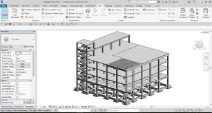
Revit is a Building Information Modelling (BIM) platform developed by Autodesk. In Revit, the structural model is three-dimensional: beams, columns, slabs, and foundations are actual 3D objects with assigned properties (material, size, reinforcement). Drawing sheets are then generated automatically from the model. Because the model is parametric, a change to a column size updates every drawing that references that column simultaneously.
Tekla Structures
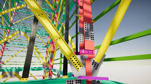
Tekla Structures is used primarily for steel-framed buildings and complex precast concrete projects. It produces fabrication-grade drawings — shop drawings — with the precision required for manufacturing. Connection symbols, bolt patterns, and weld callouts in Tekla follow very specific conventions used by steel fabricators.
Standards and Codes for Drawing Symbols
Structural drawing symbols are not freely invented. They are governed by national and international standards that define which symbol represents which element. Understanding which code applies to a given project saves time and prevents misinterpretation.
| Standard | Full Name | Region / Use |
| BS 8888 / BS EN ISO 5457 | British Standard for technical product documentation | UK and Commonwealth countries including Nigeria, Ghana, Kenya |
| BS 8110 | Structural use of concrete — detailing conventions | Widely used in Nigeria alongside BS 8888 |
| ACI 315 | Details and detailing of concrete reinforcement | USA and projects using ACI design codes |
| ISO 128 | Technical drawings — general principles of presentation | International reference standard |
| SP-34 (1987) | Handbook on concrete reinforcement and detailing | India, but referenced on some West African projects with Indian consultants |
| Eurocode (EN 1992-1-1) | Design of concrete structures, detailing rules | Europe and increasingly in Commonwealth nations |
In Nigeria specifically, projects commonly reference BS codes for detailing conventions. However, large infrastructure projects funded by international development banks may require ISO or Eurocode-compliant drawing sets. Always confirm the applicable standard at the project outset.
Real-Life Examples of Structural Drawing Symbols
Sample Beam Detailing
A typical reinforced concrete beam detail drawing shows: the beam cross-section (say 300 mm wide × 600 mm deep), the main tension reinforcement at the bottom (e.g., 4T20), compression reinforcement at the top (e.g., 2T12), and links (stirrups) at regular spacing (e.g., T10 links @ 150 c/c). The bar marks, cover dimensions, and hook details are all expressed using the symbols covered in Section 5.2 above. An engineer reading this detail can produce a complete bar bending schedule from it.
Sample Slab Reinforcement Layout
A slab reinforcement plan for a two-way slab shows span direction arrows in both X and Y directions. The bottom reinforcement in both directions is annotated (e.g., T12 @ 200 B.E.W. — 12 mm bars at 200 mm spacing, at the bottom, each way). Additional top bars are shown over supports to resist hogging moments. Strip lines across the slab indicate where bar spacing changes, and a separate detail shows how bars are lapped at construction joints.
Annotated Structural Plan
A ground floor structural plan contains all of the following simultaneously: column grid lines, column labels, beam labels with span lengths, slab panel designations, foundation type references, and level marks at key points. Being able to extract all of this information from a single sheet, without confusion between the symbol types, is the mark of a capable structural engineer or site supervisor.
Pro Tips for Students and Site Engineers
- Always carry the drawing legend with you on site. Print it separately if necessary and keep it in your site folder. A symbol that looks obvious in the office may be ambiguous under site conditions.
- Practice with actual drawings, not textbook examples. Request permission to work through completed project drawings during internships. Real drawings are more complex, more varied, and more instructive than any simplified training illustration.
- Cross-check drawings against the Bill of Quantities (BOQ). The BOQ lists quantities of materials, and those quantities should be consistent with what the drawings show. Discrepancies between the two often signal drawing errors or revisions that have not been coordinated.
- Ask questions on site before making decisions. If a symbol is unclear, the cost of asking for clarification is zero. The cost of placing reinforcement incorrectly and having to cut and re-lay it is substantial. Senior engineers and resident engineers expect juniors to ask; they do not expect juniors to guess.
- Study bar bending schedules alongside reinforcement drawings. The BBS translates every reinforcement symbol into a physical bar shape and length. Reading them together trains the eye to move fluently between symbolic notation and real steel.
- Build a personal reference sheet. As you encounter symbols on projects, note them down with their meanings and the drawing set they came from. Over time this becomes a personal reference library that reflects the codes most relevant to your work context.
Frequently Asked Questions
What are structural drawing symbols?
Structural drawing symbols are standardised graphical marks, lines, abbreviations, and annotations used in civil and structural engineering drawings to represent physical elements such as reinforcement bars, beams, columns, slabs, footings, and connections. They allow engineers, architects, and contractors to communicate technical information concisely on a single drawing sheet.
How do you read structural drawings?
Start by checking the title block to confirm the drawing number and revision. Then read the legend and general notes. Establish your grid references, identify the drawing type (plan, section, or elevation), and work through the symbols systematically. Cross-reference between the plan and any referenced section or detail drawings to build a complete picture of the structure.
What does Ø mean in structural drawings?
Ø is the symbol for diameter. When you see Ø16 or T16 in a reinforcement notation, it means a bar with a 16 mm diameter. The prefix letter (T for high-yield, R for mild steel) often indicates the steel grade, depending on the code convention being used on that project.
What is T&B in reinforcement drawings?
T&B stands for Top and Bottom. It means that reinforcement is placed at both the top and bottom faces of a structural member — typically a slab or a beam. This notation is used when the same bar size and spacing apply to both faces, avoiding the need to annotate each face separately.
Are structural drawing symbols the same worldwide?
No, they are not fully identical across every country. Core symbols — such as the centre line, dimension line, and reinforcement diameter notation — are widely consistent. However, regional standards (BS in the UK and Commonwealth, ACI in the USA, Eurocodes in Europe) introduce variations. This is why the legend on every drawing set is authoritative. Never assume a symbol means the same thing on an unfamiliar drawing without checking the legend first.
Structural drawing symbols are the shared language of the construction industry. They compress technical instructions that would otherwise fill pages of text into marks and notations that an experienced engineer can read in seconds. From a simple centre line on a foundation plan to the full reinforcement schedule of a multi-storey concrete frame, these symbols carry the information that determines whether a structure is safe, buildable, and built correctly.
For students and early-career engineers, the path to drawing fluency is straightforward: study the standards, work with real drawings, always check the legend, and never guess when a symbol is unclear. For experienced practitioners, the discipline of consistent symbol use — whether producing drawings or reading them — is one of the most direct contributions to construction quality and structural integrity.
StructoTag will continue to publish detailed guides on specific drawing types, reinforcement detailing standards, and structural design practice. Follow the platform, save this guide as a reference, and share it with colleagues who are building their drawing reading skills.
Download the StructoTag Structural Symbols Cheat Sheet for a quick-reference summary of all symbols covered in this guide. Subscribe to StructoArena for more in-depth civil engineering resources tailored to the Nigerian construction industry.